
Commercial Faucets as Engineered Building Infrastructure
Technical research for architects, plumbing engineers, specifiers, contractors, and facility teams evaluating commercial faucet systems across high-demand built environments.
Explore Technical Reference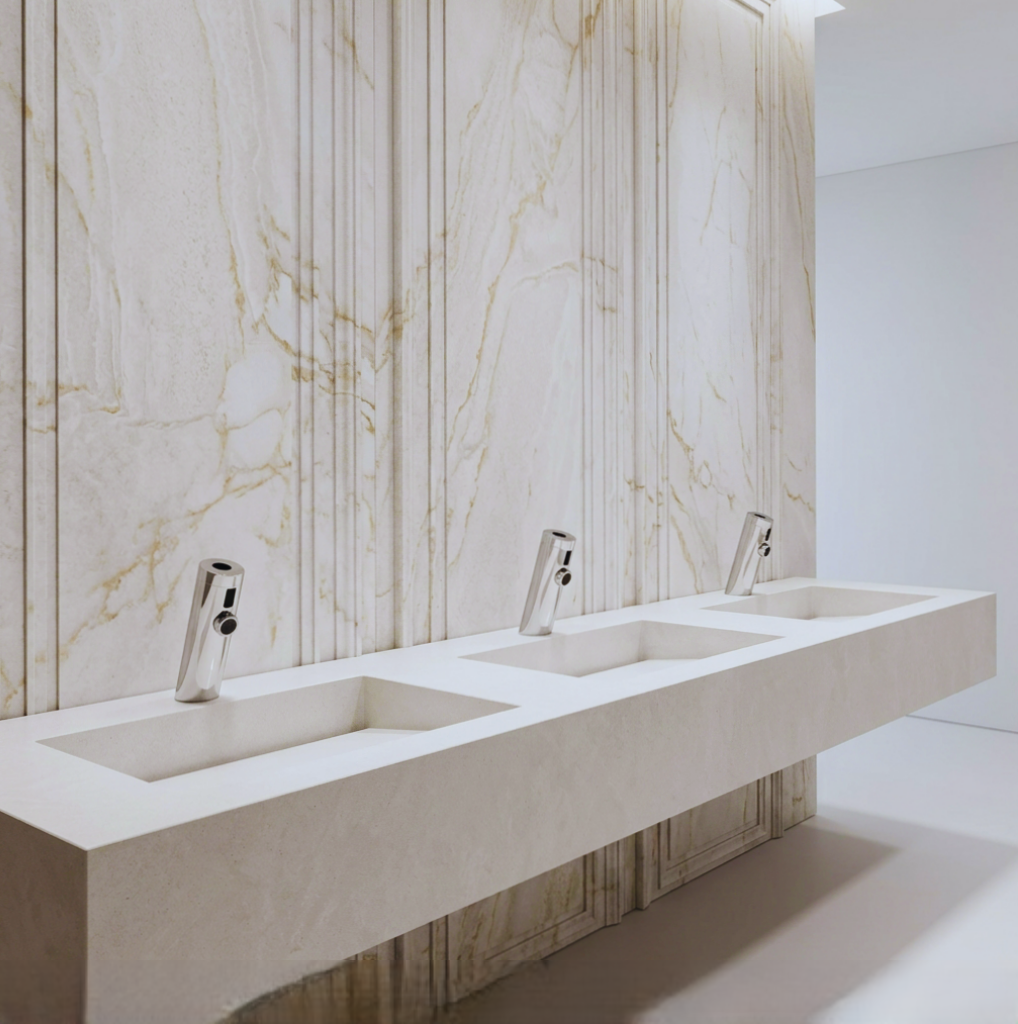
Understand Flow, Pressure & Terminal Discharge Behavior
Commercial faucets operate as terminal control points in pressurized potable-water networks. Evaluate pressure regimes, flow conditioning, outlet geometry, aeration, and demand diversity as part of the plumbing system.
Review Systems Engineering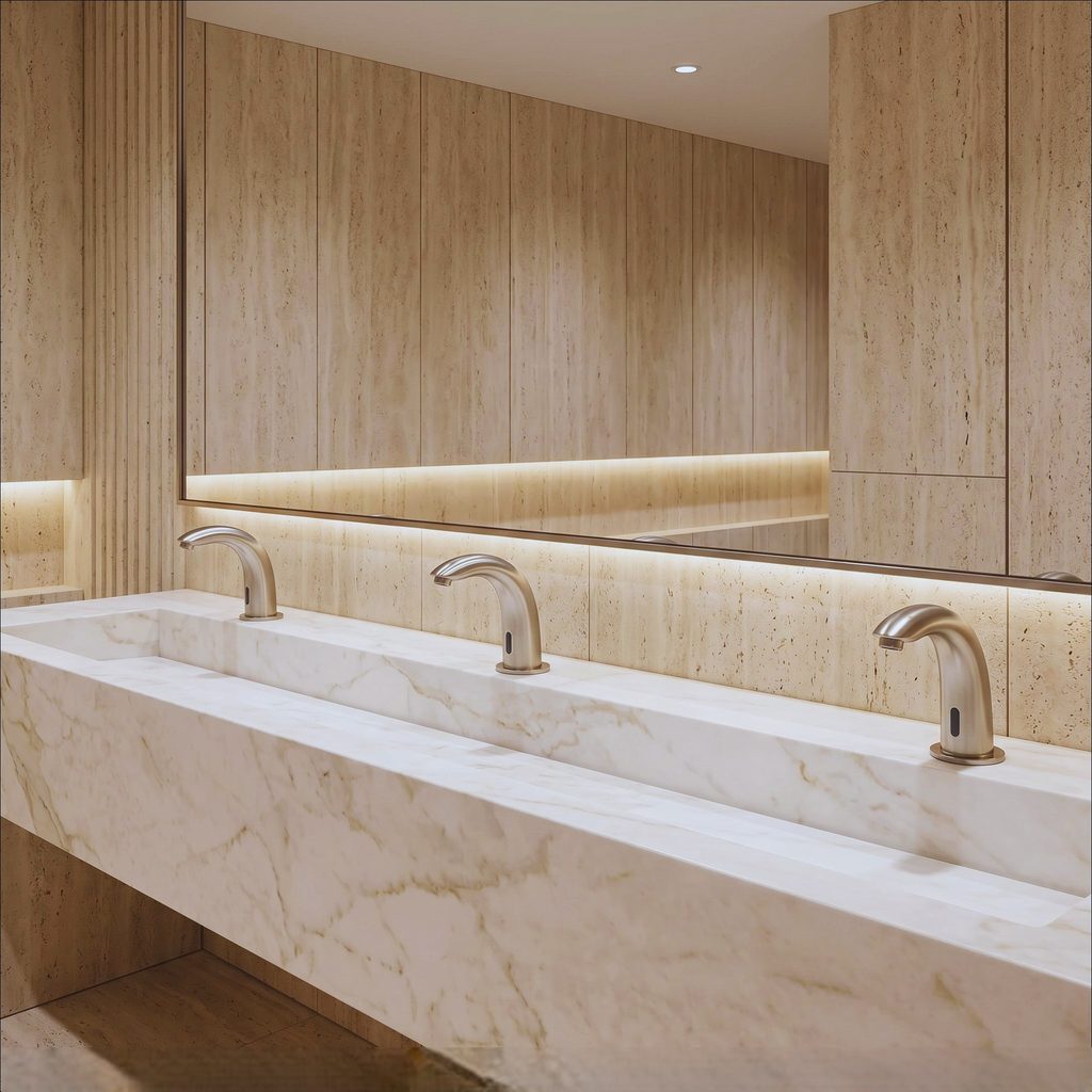
Sensor Faucets Combine Detection, Logic, Power & Valve Actuation
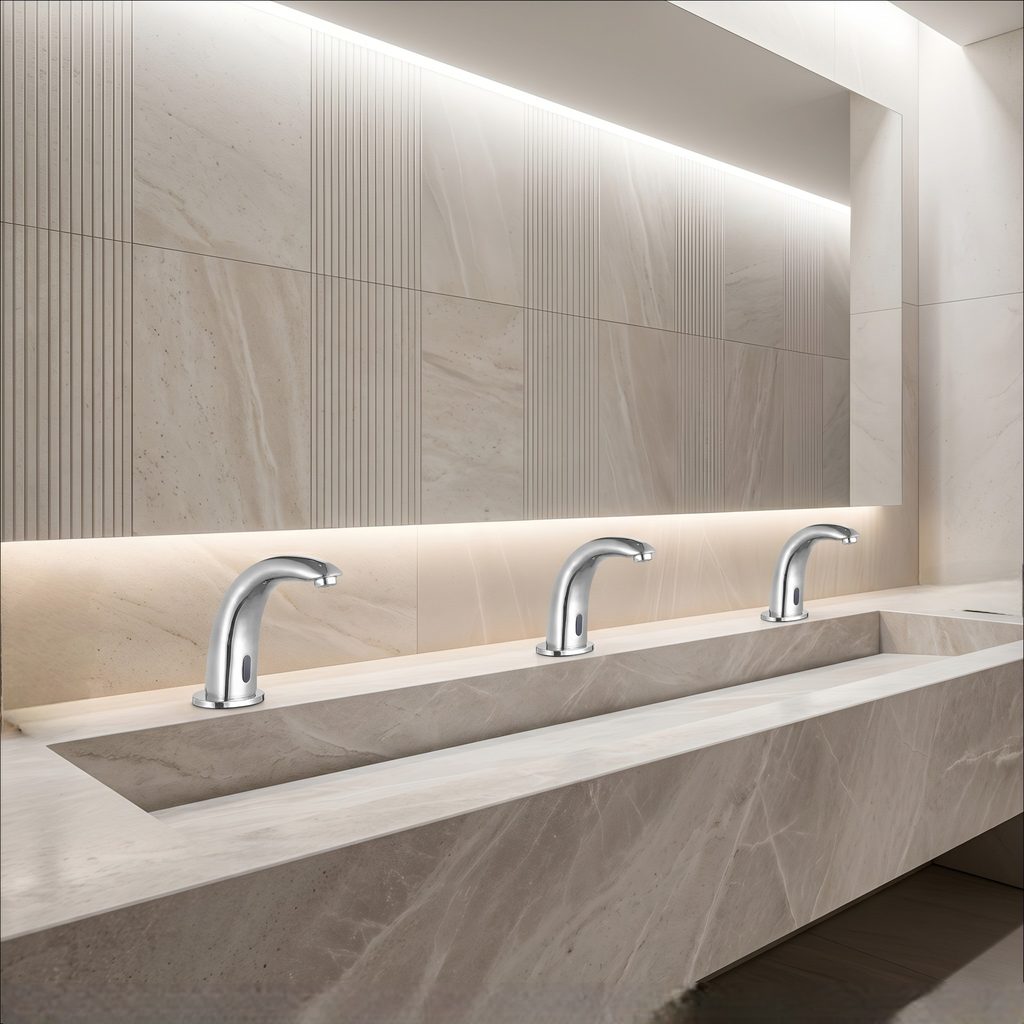
Touchless commercial faucets should be evaluated as embedded electromechanical systems—not just spouts—with sensor arrays, controllers, solenoid valves, power architecture, timing logic, and service components.
Office Touchless Faucet Guide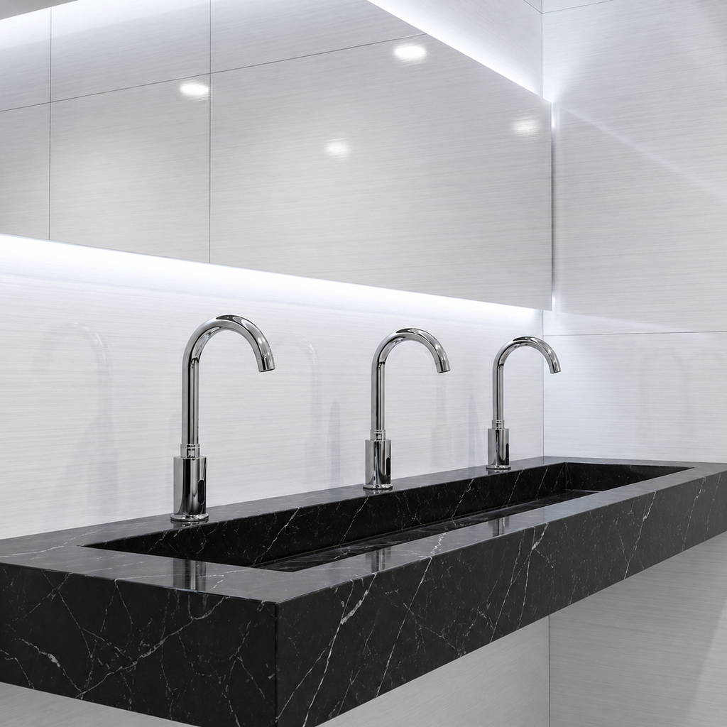
Coordinate Plumbing, Electrical, Mounting & Service Access Together
Commercial faucet performance depends on the full installation context: supply piping, pressure regulation, structural mounting, basin geometry, electrical interfaces, thermal control, drainage, and maintainable access.
Open Technical Resources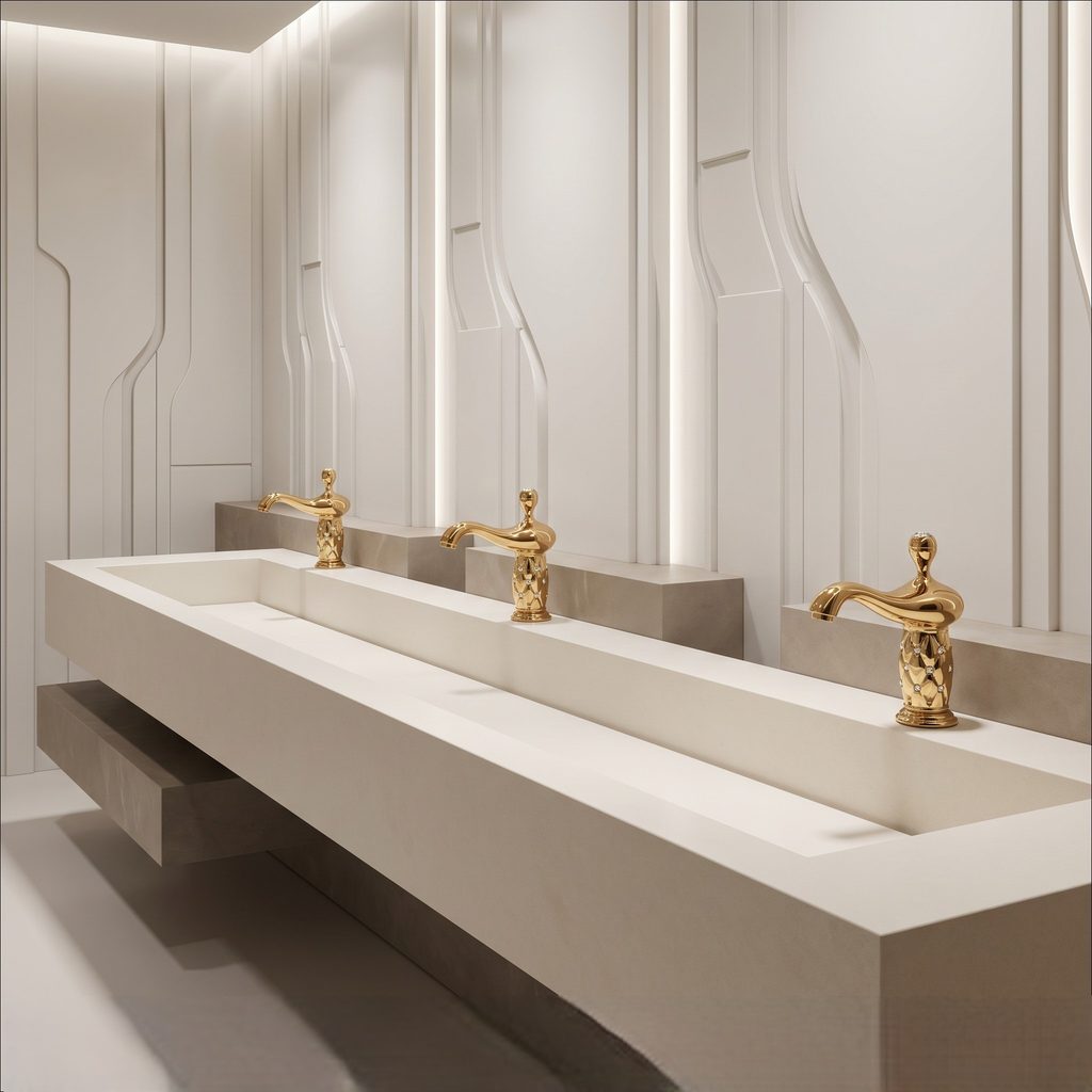
Specify for Uptime, Efficiency, Serviceability & Project Fit
Hotels, offices, airports, healthcare environments, universities, stadiums, and public facilities place different demands on faucet durability, controls, finishes, flow targets, documentation, and replacement strategy.
Review Commercial Faucet Brands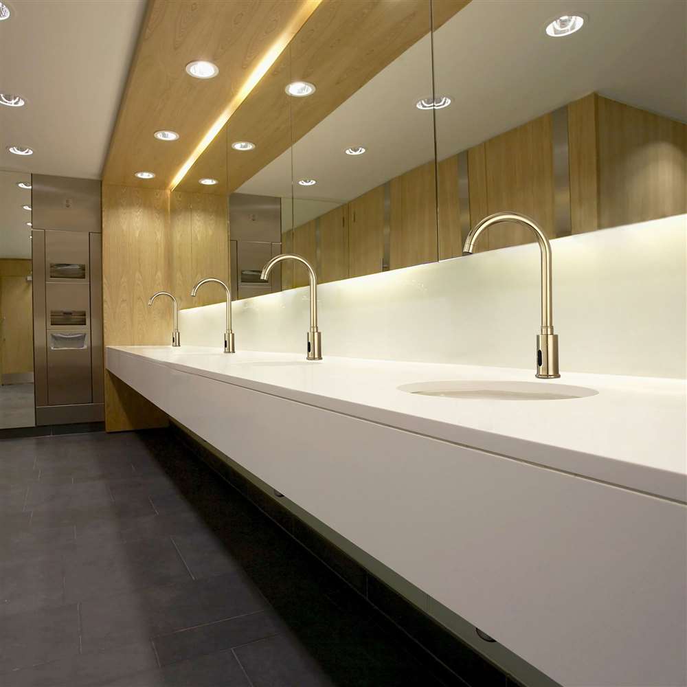
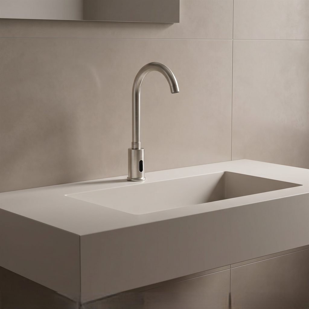
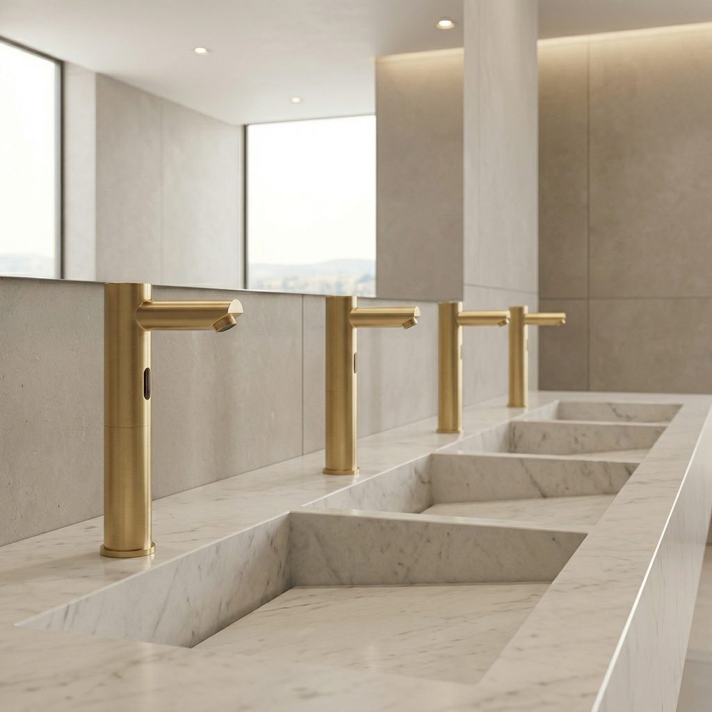
Commercial Faucet Research for Design, Specification & Operations
CommercialBathroomFaucets.com treats faucets as integrated building-system components where hydraulic behavior, controls, architecture, efficiency, reliability, and maintenance strategy converge.
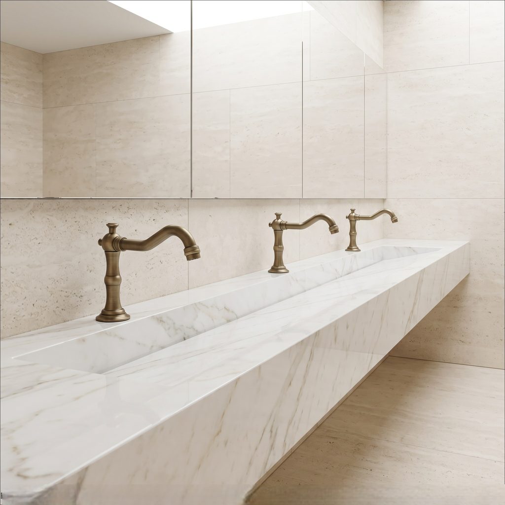
Evaluate the Faucet as a Controlled Demand Point
Connect fixture selection to upstream pressure, terminal flow control, basin geometry, mounting, accessibility, water-efficiency goals, and the facility maintenance model rather than treating the faucet as an isolated product.
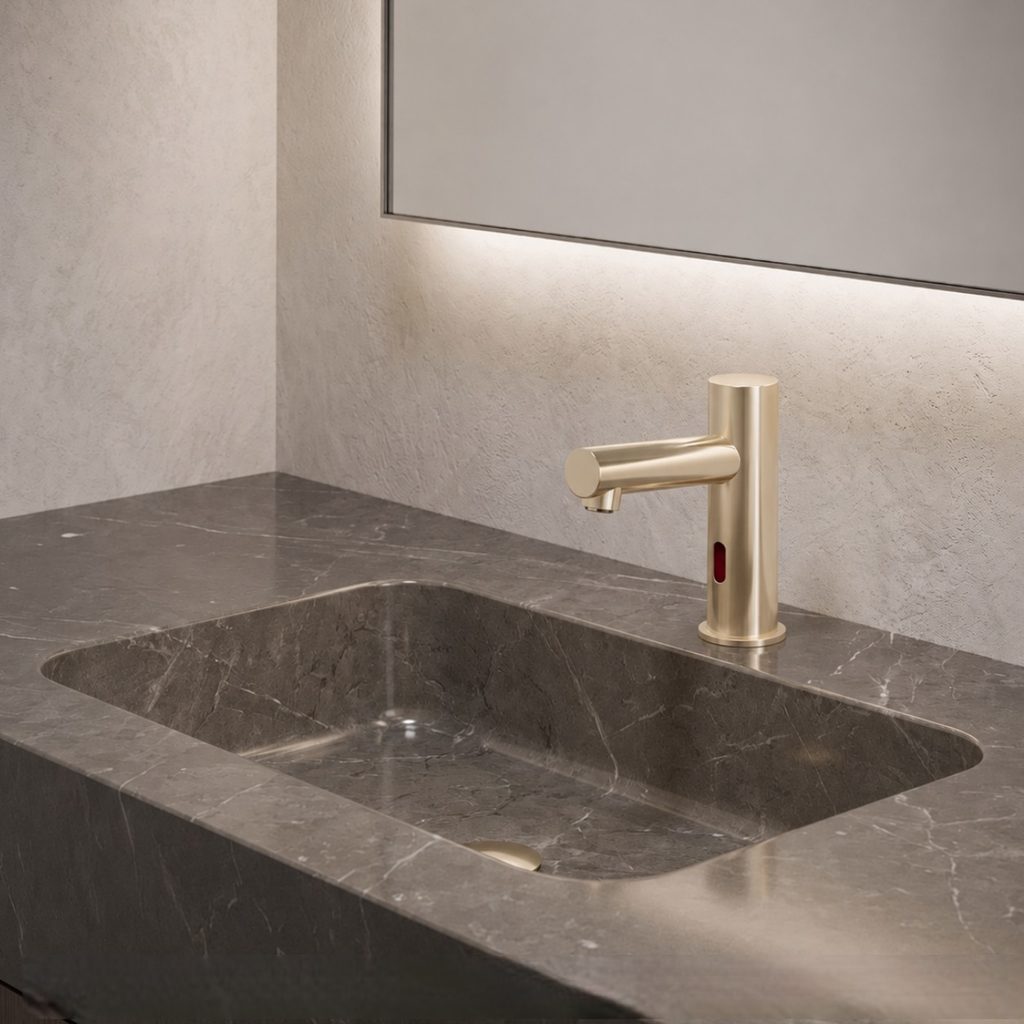
Coordinate Touchless Performance With Finish & Maintenance Standards
Corporate restroom specifications should align sensing, power, flow, finish durability, anti-vandal details, access, spare parts, and coordinated soap systems with the operating realities of tenant and core facilities.
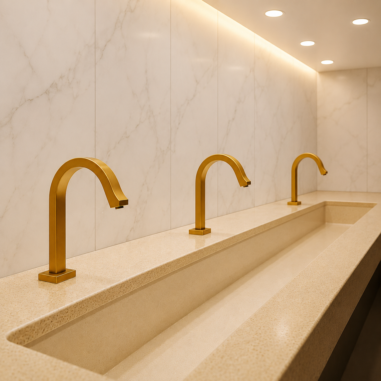
Match Faucet Platforms to Guestrooms, Public Areas & Back-of-House
Hospitality faucet selection changes by zone. Guestrooms emphasize design consistency and user experience, while public and back-of-house areas increase the importance of uptime, serviceability, vandal resistance, documentation, and parts support.
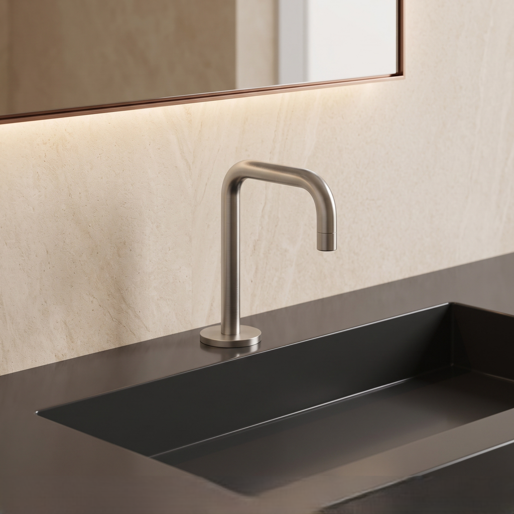
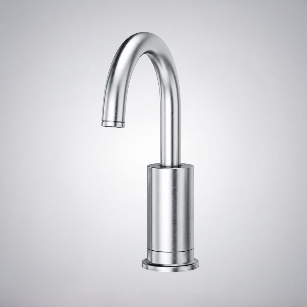
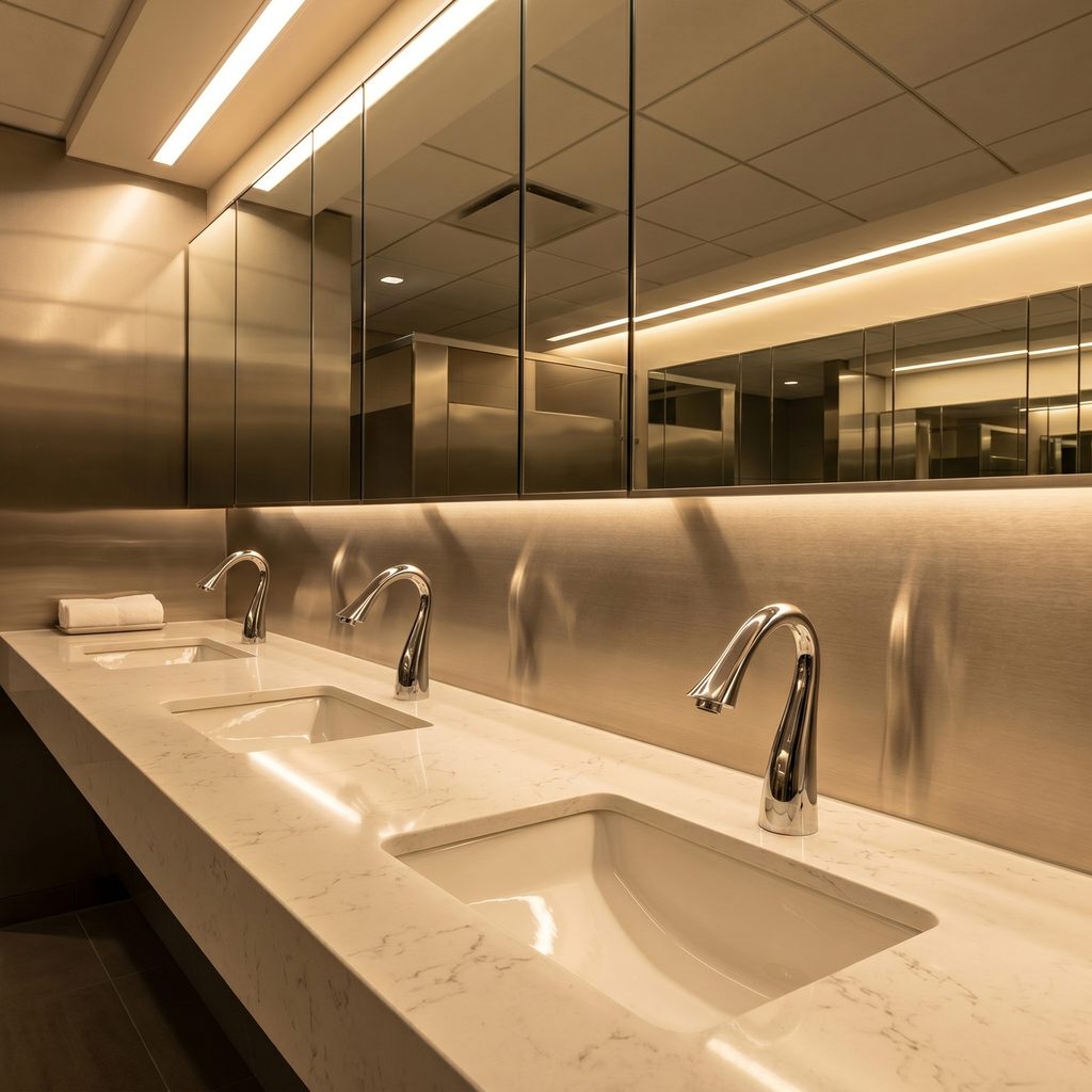
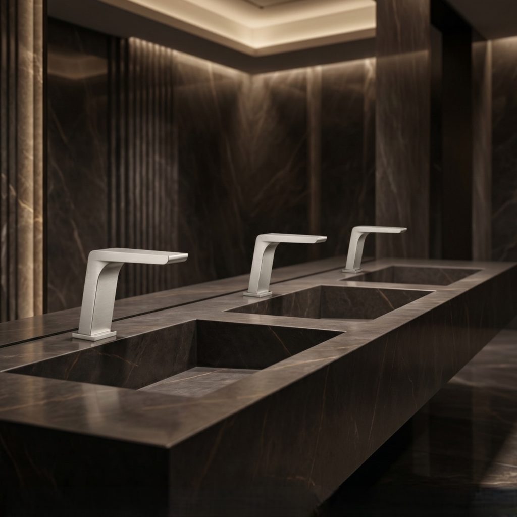
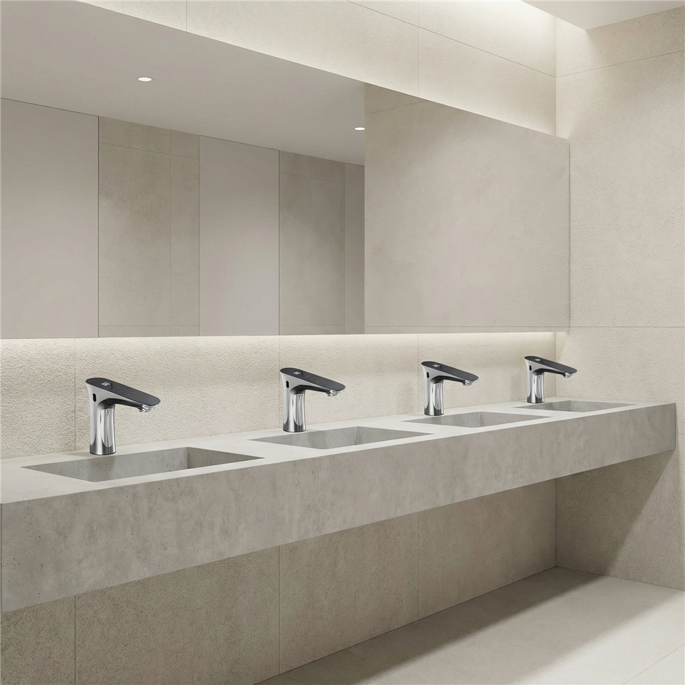
Commercial Faucet Engineering From Hydraulics to Lifecycle Service
Research topics span fluid mechanics, electronic controls, fixture demand, mounting, efficiency, reliability, maintenance, and cross-disciplinary coordination.
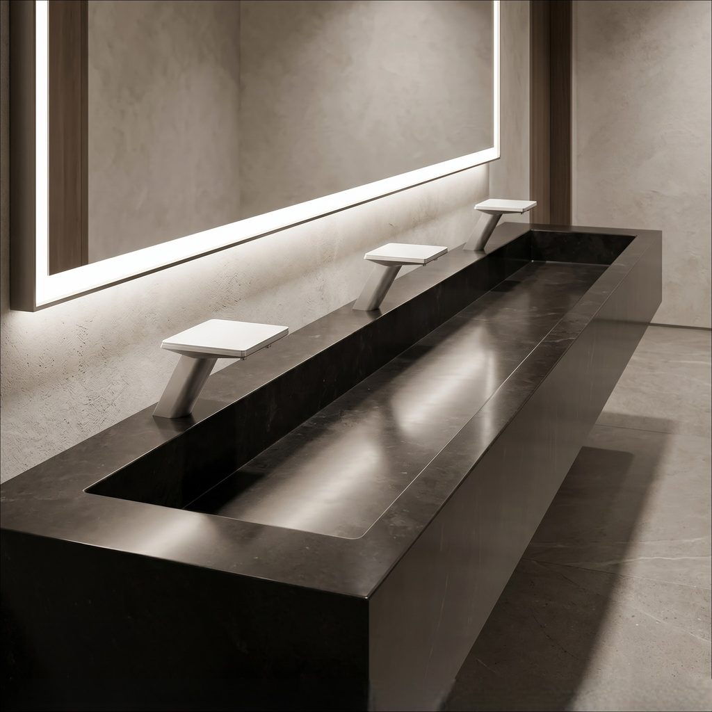
Flow & Pressure Behavior
Evaluate terminal discharge, pressure variation, flow restriction, velocity, outlet geometry, and the interaction between fixture performance and the larger plumbing network.
Hydraulic engineering →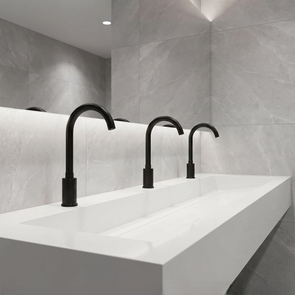
Sensor & Valve Architecture
Study infrared detection, controller logic, solenoid actuation, timing, power sources, false activation risk, and maintainable electronic components.
Touchless system guide →
Mounting & System Coordination
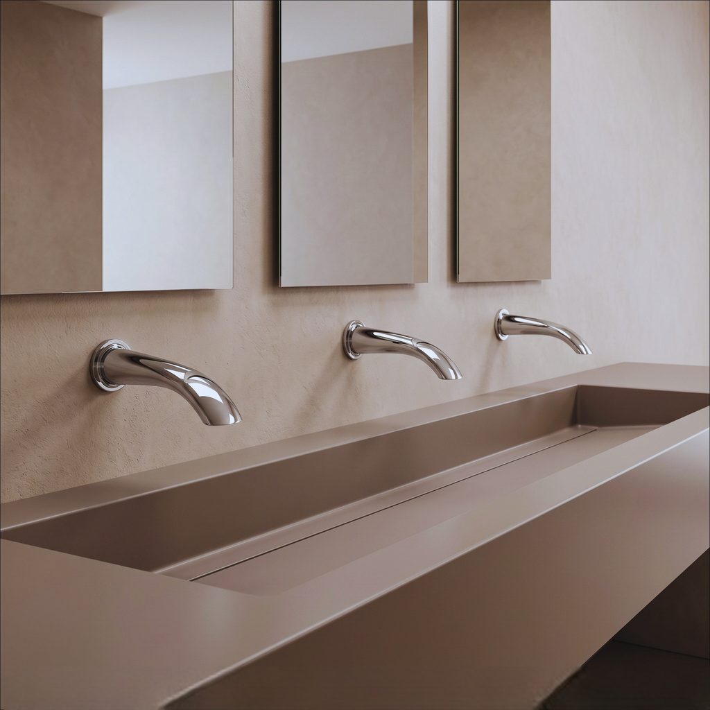
Coordinate deck or wall mounting, basin geometry, water supply, drainage, electrical interfaces, structural support, thermal controls, and service clearances.
Technical reference →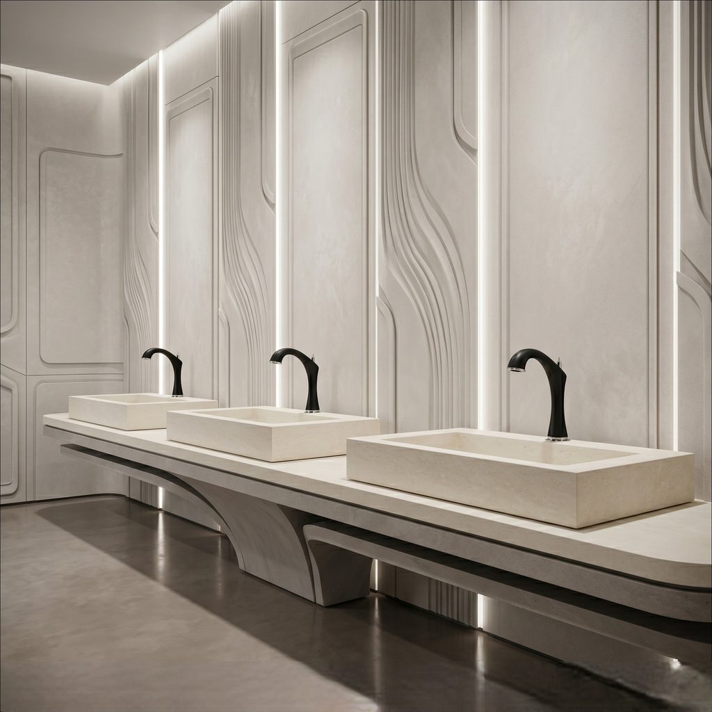
Flow Conditioning & Water Use
Review aerators, laminar outlets, pressure-compensating devices, timed operation, and control strategies that influence consumption, splash, and user experience.
Water-efficiency research →
Reliability & Serviceability
Plan for seal wear, scale, sensor fouling, solenoid fatigue, cartridge service, parts access, cleaning chemistry, maintenance cycles, and standardized replacements.
Explore lifecycle topics →
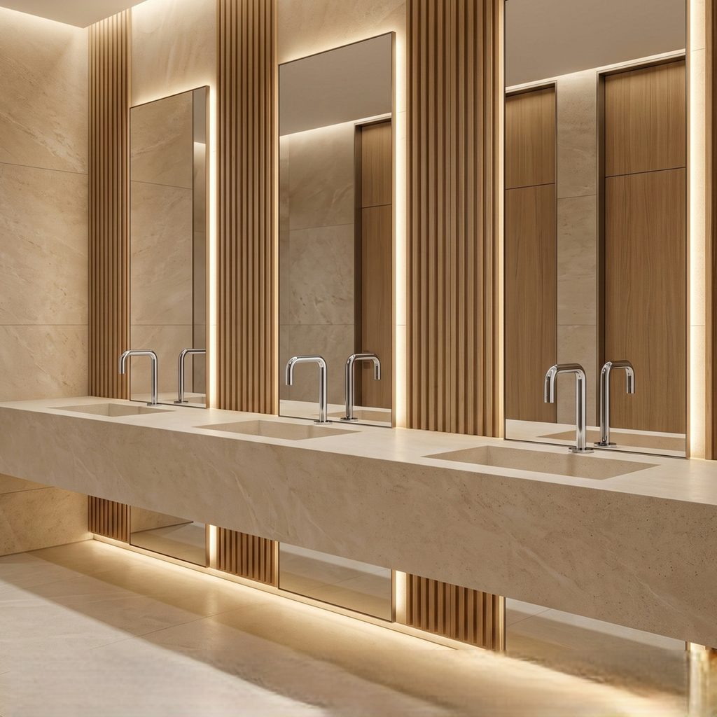
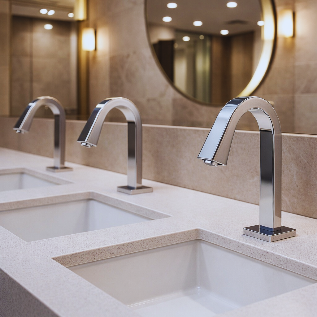
Commercial Faucet Priorities Change by Building Type & Operating Model
Traffic, finish expectations, maintenance staffing, water-management strategy, plumbing conditions, accessibility, and service access change the specification priorities from one project to another.
Design Consistency Meets Daily Maintenance
Coordinate touchless controls, finish durability, vandal resistance, access, spares, and restroom-wide visual standards for tenant and core spaces.
Office restroom guide →
Different Hotel Zones Need Different Faucet Priorities
Guestrooms can prioritize design and feel while lobby, ballroom, spa, and back-of-house areas demand different balances of durability and serviceability.
Hospitality brand research →
Hygiene Technology Works as a Coordinated Fixture Ecosystem
Touchless faucets, automatic soap dispensing, flush controls, and hand drying can be coordinated as part of a lower-contact public restroom strategy.
Hygiene technology guide →
Pressure Stability & Demand Diversity Shape Fixture Performance
Large facilities require faucet selection to work with realistic pressure conditions, simultaneous demand, flow targets, and commissioning requirements.
Systems engineering overview →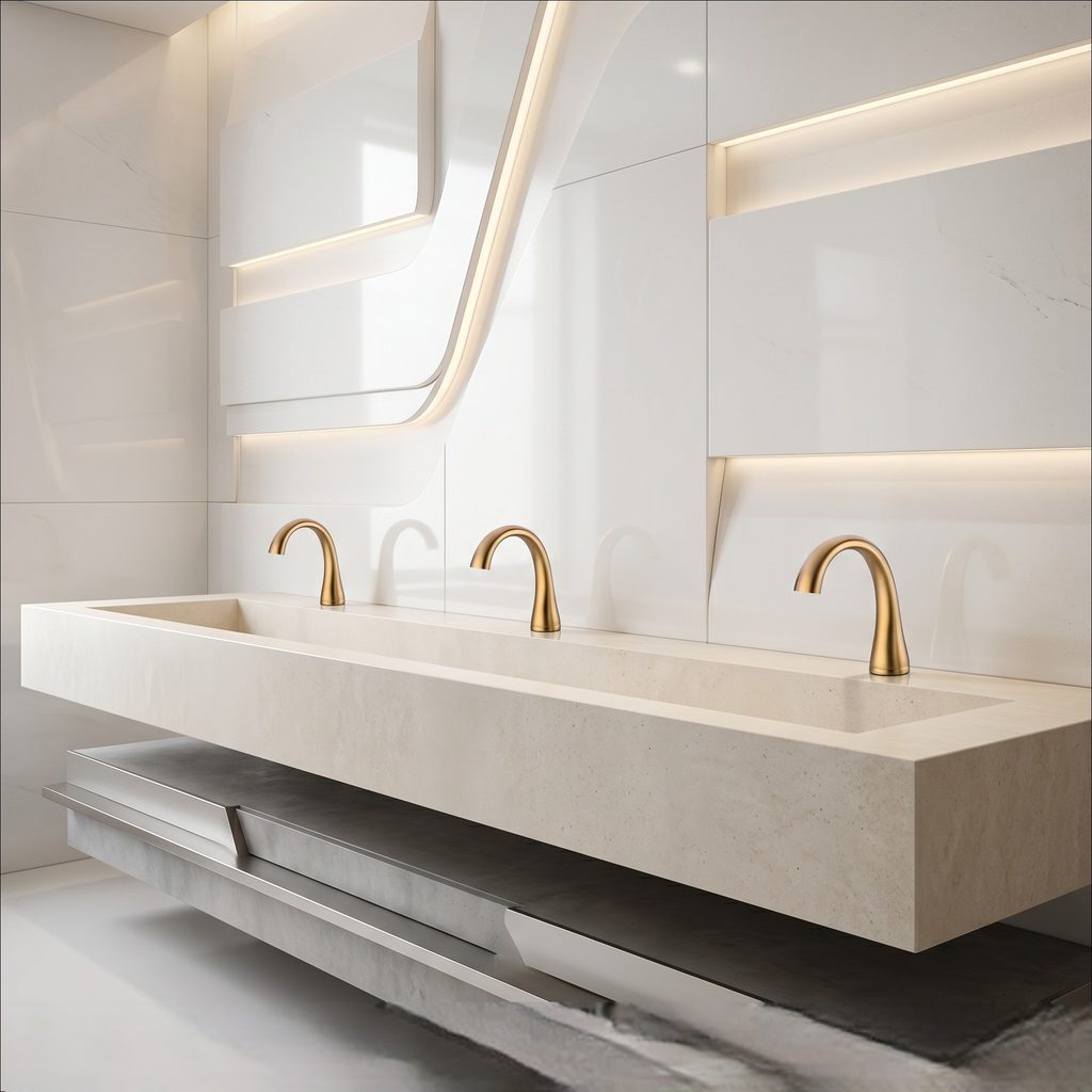
Finish, Form & Technology Still Need Engineering Discipline
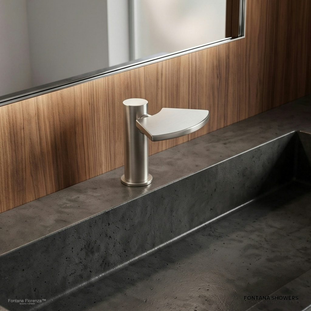
Matte black, brushed metal, chrome, and design-led spouts should be coordinated with basin geometry, coating durability, cleaning protocols, and future replacement.
Explore faucet design trends →Current Commercial Faucet Research for Real Project Decisions
Move through the technical reference framework, office touchless specification guidance, hospitality brand research, public-restroom hygiene technology, and commercial faucet design trends.
Commercial Faucet Systems Engineering
Use the site’s engineering framework to connect faucet hydraulics, controls, mounting, water efficiency, reliability, public health, and infrastructure coordination.
Explore technical reference →
Touchless Faucets for Office Restrooms
Review finish harmony, material durability, anti-vandal details, maintenance access, power planning, spare parts, and coordinated commercial touchless systems.
Read office faucet guide →
Commercial Faucet Brands for Hospitality
Examine commercial brands through hospitality priorities such as design consistency, uptime, serviceability, touchless options, documentation, and parts support.
Explore brand research →
Evolution of Hygiene Technology
Trace the shift from manual fixtures toward sensor-based faucets, soap dispensing, flush controls, and other automated systems used in modern public restrooms.
Read hygiene technology guide →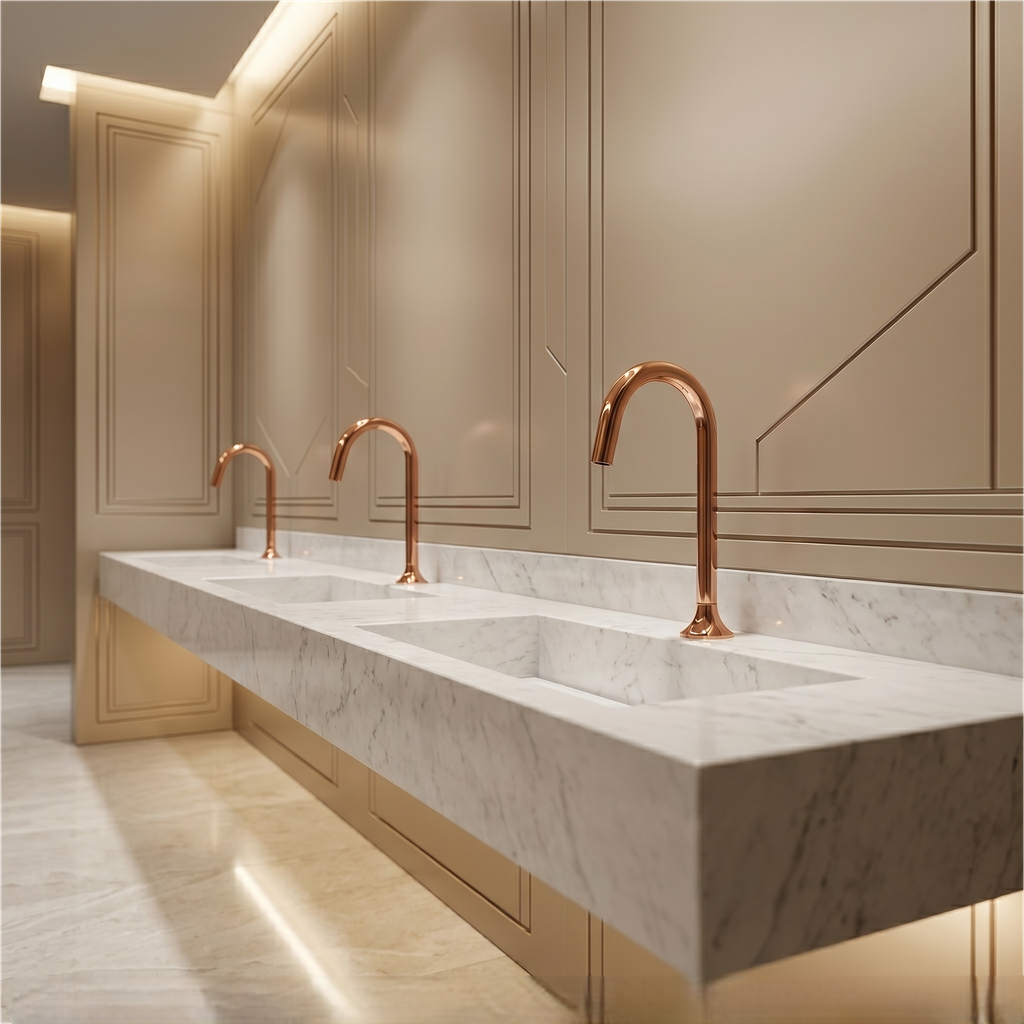
Modern Commercial Faucet Trends
Explore touchless functionality, modern fixture styling, finish directions, sustainability considerations, and the relationship between visual design and commercial performance.
View faucet trends →
Fixture Demand & Plumbing Coordination
Study commercial faucets as probabilistic demand nodes whose real performance depends on supply pressure, simultaneous fixture use, network sizing, and terminal flow control.
Review infrastructure research →